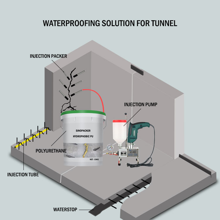
1. Waterproofing Solutions for Metro Tunnels with chemical grouting materials
Waterproofing solution is an important job to ensue the quality and safety of subway tunnel tunnel tunnel projects. In subway tunnel tunnel tunnel projects, leakage problems are often prone to occur due to factors such as high groundwater levels, high water pressure, and quality of concrete construction. Therefore, waterproofing and leak-proofing work is crucial with chemical grouting materials.
If you still don’t know how to make a waterproofing solution plan, the following shares solutions for tunnel waterproofing construction.
1.1 Compilation principles
The scientific program design is guided by treating the root cause, treating the symptoms as a supplement, treating both the symptoms and the root cause, and comprehensive management, and follows the principle of "combination of prevention, drainage, interception, and blockage, a combination of hardness and softness, adapting measures to local conditions, and comprehensive management".
A targeted and feasible comprehensive treatment plan must be designed based on the actual situation of water leakage in each location.
The plan should consider the influence of multiple factors, and conduct specific construction plan design based on the principles of pertinence, reliability, economy, operability, and predictability.
The plan should also be based on the combination of points, lines and surfaces, coupled with the construction technology of waterproof materials, to form a complete waterproofing system on the leakage water surface layer that meets the comprehensive waterproofing requirements of the project.
While ensuring the quality and reliability of leakage control, the plan should take into account the corrosion of corroded steel bars within the structure, and require that the waterproof materials used must be non-toxic, odorless, and non-polluting to the environment.
1.2 Compilation basis
- Design drawings, construction site conditions and on-site survey data provided by Party A.
- Specifications for acceptance of construction quality of underground waterproofing projects.
- Specifications for construction and acceptance of underground railway projects.
- Technical specifications for underground engineering waterproofing.
- Building Waterproofing Engineering Manual.
Construction Engineering Quality Inspection and Assessment Standards.
2. Chemical grouting construction introduction
In addition to concentrated water leakage in the floor of the subway tunnel station, water leakage mainly occurs from side wall construction joints and side wall vertical cracks. Water leakage is mainly caused by cracks in the floor, honeycomb pits, and circumferential cracks in the tunnel, followed by water leakage from construction joints and vertical cracks in the side walls.
3. Construction damage analysis
According to the current situation of water leakage, it is divided into the following five situations for analysis.
3.1. Honeycomb pitted surface leakage phenomenon
The formation of honeycomb pits is directly related to concrete construction. The main reason is that vibration leakage or insufficient vibration time occurs during construction. Some of these honeycomb pits exist independently in concrete structures, while others are continuous. Therefore, when leakage or leakage occurs, it will appear as sheet leakage or leakage in strands.
3.2. Load deformation cracks and water leakage
Load deformation cracks are caused by two situations: First, when the concrete structure of the tunnel floor has not reached the strength required by the design, it is caused by deformation cracks caused by being squeezed by the enclosure structure. Coupled with the uneven settlement of the tunnel, the tunnel has circumferential cracks. Cracks; the second is cracks caused by overload stacking on the back of the concrete wall even if the concrete has reached the design strength. The cracks that appear in the latter are generally more obvious and are penetrating cracks.
3.3. Water leakage at joints between old and new concrete
When pouring concrete on the original concrete structure, the surface of the original concrete foundation was not roughened or was not cleaned after roughening, or the concrete mixture was poured on the original concrete foundation without being rinsed with water. This will cause a seepage and leakage gap to form between the old and new concrete joints.
3.4. Water leakage phenomenon from self-stress cracks in concrete.
Self-stressed cracks in concrete are often easily produced on concrete wall panels. They are generally in the form of cracks that run up and down. They show regular cracks on the entire concrete wall, usually 3 to 5 meters apart. This kind of crack is caused by the self-stress of concrete. The reason is that when the heat of cement hydration reaches a certain level, the expansion stress of concrete begins to disappear and the concrete begins to shrink. This kind of shrinkage is uniform shrinkage, so under such conditions, the cracks of the concrete wall panels show regular cracks.
3.5. Water leakage phenomenon in concrete deformation joints.
During the construction process, the installation of the waterstop was not firm, causing the waterstop to shift during tamping. Another situation is that the concrete near the waterstop is leaked or not compacted, causing leakage holes in the concrete on both sides of the deformation joint.
4. Chemical grouting deployment and measures
Based on the analysis of the causes of water leakage, the following five leakage plugging measures are taken to deal with it.
4.1. Aiming at the phenomenon of water leakage on honeycomb pitted surface.
Find the main leaking points, mark them, and use an impact electric hammer to drill holes with a hole diameter of 10mm and a hole depth of 100~300mm. Then seal the remaining leaking points, then pressure-inject ultra-fine cement slurry into the holes, and add a certain amount of cement slurry. amount of micro-expansion agent, and then add an appropriate amount of water glass according to the pressure injection situation.
4.2. Aiming at the phenomenon of load deformation cracks and water leakage
Two measures are taken to plug the leak. One is to use a grouting method that combines grouting inside the lining and grouting outside the lining in the tunnel hole for cracks that are still developing. First, a dual-liquid grouting pump is used to pressure-inject ordinary Portland cement P.O32.5 outside the lining. An appropriate amount of water glass is added according to the grouting situation, and then water-soluble polyurethane slurry is pressure-injected inside the lining. The other method is to press-inject ultra-fine cement slurry for cracks that no longer develop or develop slowly. A certain amount of micro-expansion agent is added to the cement slurry, and an appropriate amount of water glass is added according to the injection situation.
4.3. Aiming at water leakage at joints between old and new concrete
Use pressure injection of moisture-curing epoxy resin slurry to plug leaks.
4.4. Aiming at the phenomenon of water leakage from self-stress cracks in concrete
Two measures are taken. One is to inject moisture-curing epoxy resin slurry into leaking cracks or wet joints to plug leaks. The other is for dry joints, injecting ordinary epoxy resin slurry to seal the joints
4.5. Aiming at the phenomenon of water leakage in concrete deformation joints
First, three high-pressure jet grouting piles are added to the deformation joints outside the structure to isolate the deformation joints from the outside world, and then ultra-fine cement slurry is injected into the structure where the concrete is not dense near the deformation joints.
5. Chemical grouting construction technology
A grouting method that combines internal lining grouting and lining external grouting is adopted in the tunnel.
5.1. Tunnel lining external chemical grouting
The external grouting of tunnel lining is divided into two situations: construction outside the tunnel and construction inside the tunnel. For construction outside the tunnel, a triple-tube high-pressure jet grouting pile machine is used to inject cement, epoxy resin and water into the soil outside the deformation joint, and the soil is consolidated through stirring with blades and soil particles to achieve the purpose of water stop. The construction inside the hole is to drill through the structural bottom plate or side wall with a pneumatic drill, drill a small hole of ф40mm, and inject cement slurry or cement-epoxy resin double liquid slurry into the soil near the outside of the hole to block the leakage channel and make the soil Consolidation to achieve the purpose of water stop.
5.2. Epoxy resin mortar mix ratio
|
Item |
Epoxy |
Acetone |
Quartz powder |
Sand(particle size 0.25~0.55㎜) |
Ethylenediamine |
|
Epoxy resin mortar |
100 |
10 |
270 |
540 |
6~8 |
The compressive strength of this kind of mortar can reach 68.6~88.3MPa, and the tensile strength is 14.7~19.6 MPa, but it is appropriate to prepare no more than 1.5kg at a time. When preparing epoxy mortar, first put a certain amount of epoxy resin in the container. When the resin has a high consistency, it should be heated to about 40°C, then add the diluent and stir evenly, then add the curing agent, stir thoroughly, and finally add quartz powder or porcelain powder, sand, and stir evenly. The oxygen mortar should be used up within 40 minutes.
5.3. Grouting hole layout
Layout
During construction outside the tunnel, three high-pressure jet grouting piles were arranged outside the deformation joints of the side walls in order to isolate the deformation joints from the outside world.
The holes constructed in the cave are set according to the cracks and water leakage conditions.
Drilling holes for construction in the cave
The drill holes are positioned according to the layout of the bored piles, and pneumatic drilling is used to form the holes. Before drilling, manual trenching is used to position the holes so that structural steel bars can be avoided during drilling. Hole diameter: Ф40, hole depth: the drill hole exceeds the outside of the structural side wall, and the depth of the buried pipe does not exceed the outside of the structural side wall.
5.4. Processing and installation of grouting
Injection hose processing
The grouting pipe is made of φ20mm steel pipe, the length of the grouting pipe is 0.8m, and the tail is made into a threaded joint.
Installation of injection hose pipe
After drilling is completed, use high-pressure air to wash the hole, and manually install the grouting pipe. In order to prevent the gap between the grouting pipe and the hole from running out, cotton silk should be filled within 0.3m to 0.4m at the end of the pipe, and the leakage should be plugged with quick-setting Agent seals and buries the pipe.
A grout stop valve is installed at the joint of the small conduit so that it can be closed in time to prevent grouting back when the grouting is completed.
5.5. Chemical Grouting materials injection
Tunnel grouting follows the "bottom to top" principle, with the tunnel floor constructed first, then the tunnel side walls, and finally the tunnel roof. The grouting pressure should not exceed 1.0Mpa, and the grouting pressure should be increased step by step while following the principle of thinning first and then thickening.
During chemical grouting, the mixed cement slurry must be filtered with a fine screen before it is allowed to enter the grouting barrel. During grouting, holes without water should be injected first, and then holes with water should be injected. In case of grout channeling or a small amount of grout running, the grouting interval should be increased. Large, if there is strand-like slurry, the cement slurry injection can be suspended and the cement ~ water glass double liquid slurry can be injected.
Since the grouting amount is difficult to determine, the grouting pressure for each grouting pipe must be completed when the grouting pressure reaches 1.0MPa. After each grouting is completed, close the grouting valve, unscrew the pipe and connect it to another grouting pipe to continue grouting. After the slurry solidifies, unscrew the gate valve and clean the gate valve to facilitate recycling.
During the grouting process, a dedicated person will record the grouting situation and adjust the grouting pressure and speed according to the actual situation to ensure the grouting effect. 3 to 5 days after grouting is completed, if there is still water seepage, re-inject until the water-stopping effect is achieved.
Data sheet of grouting injection
Item |
Unit |
Index |
Injection Pressure |
MPa |
1.0 |
Hole depth |
m |
0.5~0.7 |
Hole diameter |
m |
Ф40 |
Distance |
m |
Based on working |
Injection quantities |
m3 |
Based on working |
5.6 Grouting inside tunnel lining
- Process flow
Preparatory stage
Base surface cleaning → Seal the cracks in the buried pipe → Comprehensive sealing along the entire seam → Gas test to check the sealing condition → Wait for irrigation.
Grouting
Ingredients, connect the pipeline → Add material → Close the pressure reducing valve → Pressurize the grout → Block the grout immediately when the nearby nozzle comes out → Continue the pressure injection until the grout can no longer be pressed → Maintain the pressure → Block the grout nozzle → Open the pressure reduction valve, pull out the hose → cleaning tool.
2. Operation steps and methods
Base surface treatment: Use a small hammer, chisel, wire brush, etc. to remove loose slag, floating slurry, etc. on the concrete surface. When cleaning, be careful not to block the cracks. Do not rinse with water, but use cotton gauze dipped in alcohol to scrub.
Grooving and drilling along the crack: Carve out a V-shaped groove with a width and depth of 10 to 20 mm along the crack, and drill holes at the beginning and end of the crack and at the bifurcation. In addition, the crack sections with a width of less than 0.2 mm should be spaced 300 mm apart. Drill holes at intervals of 500mm in crack sections with a width of 0.2mm or more. The slot holes after picking must be cleaned. Use epoxy resin glue or leak-stopping agent to bury a small φ8 mm aluminum pipe in the cleaned hole.
Sealing: To ensure the success of grouting, the crack must become a closed body. Fill the grooved cracks with epoxy resin glue or leak-stopping agent. Small aluminum pipes are firmly fixed with epoxy resin glue or leak-proofing agent. Be careful not to block the pipe mouth.
Gas test: After the epoxy resin cement has hardened, perform a gas test. The purpose of air testing is to blow out the dust remaining in the cracks; to check the penetration; and to check whether there is air leakage in the sealing layer. How to test the gas: Brush soapy water on the sealing layer. If air leaks, soap bubbles will form, and the leak must be repaired with cement or leak-stopping agent.
Operation sequence: Correctly determine the shape and characteristics of the interior of the crack based on the gas test records, and formulate a grouting plan. Generally, grouting should follow the principle of gradual progress from bottom to top or from one end to the other to prevent air from being mixed into the grout and affecting the compactness of the grout.
During the grouting process, if grout leakage occurs, immediately relieve the pressure and stop grouting, and use a quick-setting leak-stopping agent to immediately block the leakage and stop the grout.
Cleaning: Immediately after grouting, clean tools with acetone and alcohol before the grout cures. The small aluminum tubes adhered to the concrete surface can be knocked off after the slurry in the aluminum tubes solidifies to remove the residue.
3. Material composition and preparation method
Ultra-fine cement slurry. The specific surface area of ultrafine cement should be greater than 7000m2/g. Add a certain amount of micro-expansion agent (aluminum powder or UEA micro-expansion agent), and add an appropriate amount of water glass according to the needs of the injection situation.
Water-soluble hydrophilic polyurethane foam. It is diluted by adding an appropriate amount of acetone to the finished hydrophilic polyurethane solution.
Moisture-curing epoxy resin slurry and mastic: the proposed formula (weight ratio) is as follows.
Item |
Epoxy |
Diethanolamine + Salicylic Acid |
Ketimine B + divinylamine |
Dibutyl phthalate |
Cement |
Quicklime |
1 |
100 |
10+5 |
4+8 |
5 |
||
2 |
100 |
10+5 |
0+10 |
10 |
50 |
20 |
3 |
100 |
10+(3~5) |
16+0 |
100 |
20 |
|
4 |
100 |
10+5 |
10+5 |
50 |
20 |
During preparation, first dissolve salicylic acid in diethanolamine, then add ketimine into the resin, and stir evenly respectively. Stir the two together, then add filler and mix evenly.
Ordinary epoxy resin slurry and clay: The proposed formula (weight ratio) is as follows.
Item |
Epxoy |
Acetone |
Dibutyl phthalate |
Ethylenediamine |
Cement |
1 |
100 |
10~40 |
10 |
8~12 |
5 |
2 |
100 |
10 |
10 |
12~16 |
300 |
Except for epoxy resin and cement, which need to be weighed during preparation, all other materials can be converted into weights using measuring cups. In order to avoid sudden heat and explosion of the slurry, except for the curing agent which is added before use, the remaining main and auxiliary agents must be mixed into semi-finished products first.
Item |
Name |
Pieces |
Note |
1 |
Drill |
3 |
Ф38 drill |
2 |
2 |
0~7mpa、50L/min |
|
3 |
Pail |
2 | |
4 |
Air compressor |
2 | |
5 |
Mortar Pump Mixer |
2 | |
6 |
Hand-pressed grouting tank |
3 |
Including gauge |
7 |
High-pressure injection hose |
50 |
|
8 |
10000 |
||
9 |
Impact drill |
2 |
Drillф10mm、13mm, Rod length500mm |
10 |
Wire brush |
8 |
|
11 |
Empty the brush |
30 |
|
12 |
Glue handle pliers |
2 |
|
13 |
Measuring cup |
2 |
|
14 |
Case scale |
2 |
|
15 |
Rubber gloves |
30 |
|
16 |
Cloth gloves |
50 |
|
17 |
Protection wear glasses |
16 |
|
18 |
Mask |
16 |
|
19 |
Hammer |
6 |
6. Safety of chemical grouting measures
6.1 We must adhere to the policy of "safety first, prevention first". The person in charge of the construction team must make safety work the first priority, strengthen employee safety awareness education, strengthen the safety assurance system, and implement the safety production responsibility system.
6.2 Personnel entering the construction site must wear safety helmets; it is strictly prohibited to wear slippers, high heels, and slip-on shoes to work; it is strictly prohibited to drink alcohol before or during work.
6.3 Personnel in special types of work such as electricians and machinery operators must hold certificates to work. Personnel outside this type of work are strictly prohibited from operating in violation of regulations.
6.4 Construction workers must also wear protective glasses and masks when grouting.
6.5 The operating platform must be safe and reliable and equipped with solid guardrails. Tools must be properly placed after use to prevent them from falling.
6.6 Construction power lines must be erected by full-time electricians. Electrical equipment should be tested before use, and "one machine, one gate, and one leak" should be implemented. Electricians must be familiar with the "Technical Specifications for Safety of Temporary Electricity Use at Construction Sites" and operate in accordance with the regulations. There must be a full-time electrician on duty at the construction site.
6.7 The casing, handle, load line, plug, switch, etc. of hand-held power tools must be intact. They must be inspected without load before use. They can be used only after they are operating normally. Hand-held power tools should be Class II tools with double insulation or reinforced insulation protection measures. , and a leakage protector should be installed; the shell, pressure gauge, load line, etc. of the grouting machine must be intact, and the pressure gauge should be calibrated before it can be used. The grouting materials and their mix ratios should meet the program requirements to prevent blockage. The pipe may affect the grouting quality.
6.8 If you accidentally splash the slurry into your eyes, wash them immediately with clean water and send them to the hospital for treatment if necessary.
6.9 The grout and aluminum pipes adhered to the concrete surface as well as the garbage after grouting must be cleaned up.